HSRP Questions 4
Here you will find answers to HSRP Questions – Part 4
Question 1
Which three of the following network features are methods used to achieve high availability? (Choose three)
A. Spanning Tree Protocol (STP)
B. Delay reduction
C. Hot Standby Routing Protocol (HSRP)
D. Dynamic routing protocols
E. Quality of Service (QoS)
F. Jitter management
Answer: A C D
Explanation
STP, HSRP and dynamic routing protocols provide backup paths to reach the destination and achieve high availability.
Note: Quality of Service (Qos) only prioritizes specific type of data over other types and provides no high availability.
Question 2
Which command will ensure that R2 will be the primary router for traffic using the gateway address of 172.16.15.20?
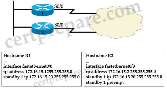
A. On R2 add the command standby 1 priority 80
B. On R1 add the command standby 1 priority 110
C. On R1 add the command standby 1 priority 80
D. On R2 remove the command standby 1 preempt
Answer: C
Explanation
By default the priority value of HSRP is 100 so in order to ensure that R2 will be the primary router for traffic using the gateway address of 172.16.15.20 we can set the priority of R2 higher than 100 or set the priority of R1 lower than 100 -> only C is correct.
Question 3
Which command will need to be added to External_A to ensure that it will take over if serial 0/0 on External_B fails?
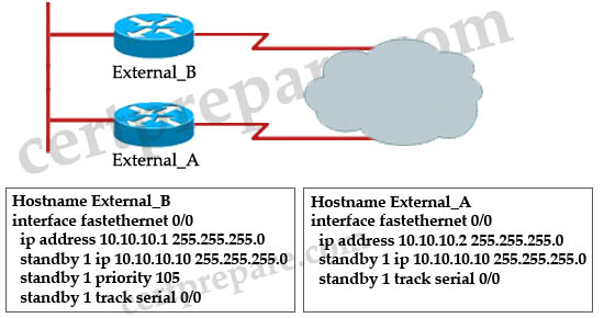
A. standby 1 priority 130
B. standby 1 preempt
C. standby 1 track fastethernet 0/0
D. standby 1 track 10.10.10.1
Answer: B
Explanation
The “standby 1 preempt” command on External_A router will make External_A take over the active state if it learns that its priority is higher than that of External_B router. In this case, when S0/0 interface of External_B fails, its priority will be 105 – 10 = 95, which is smaller than the default priority value (100) on External_A.
Question 4
Refer to the exhibit and the partial configuration on routers R1 and R2. Hot Standby Routing Protocol (HSRP) is configured on the network to provide network redundancy for the IP traffic. The network administrator noticed that R2 does not became active when the R1 serial0 interface goes down. What should be changed in the configuration to fix the problem?
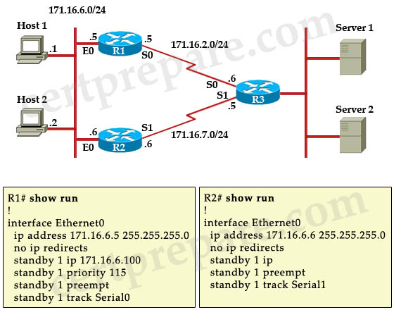
A. The Serial0 interface on router R2 should be configured with a decrement value of 20.
B. The Serial0 interface on router R1 should be configured with a decrement value of 20.
C. R2 should be configured with a standby priority of 100.
D. R2 should be configured with a HSRP virtual address.
Answer: B
Explanation
When Serial0 of R1 goes down, the priority of R1 is still higher than that of R2 (115 – 10 = 105 > 100) so we should configured the decrement value of 20 on R1 with the command: standby 1 track Serial0 20.
Question 5
Three Cisco Catalyst switches have been configured with a first-hop redundancy protocol. While reviewing some show commands, debug output, and the syslog, you discover the following information:
| Jan 9 08:00:42.623: %STANDBY-6-STATECHANGE. Standby: 49:Vlan149 state Standby -> Active Jan 9 08:00:56.011: %STANDBY-6-STATECHANGE. Standby: 49:Vlan149 state Active -> Speak Jan 9 08:01:03.011: %STANDBY-6-STATECHANGE. Standby: 49:Vlan149 state Speak -> Standby Jan 9 08:01:29.427: %STANDBY-6-STATECHANGE. Standby: 49:Vlan149 state Standby -> Active Jan 9 08:01:36.808: %STANDBY-6-STATECHANGE. Standby: 49:Vlan149 state Active -> Speak Jan 9 08:01:43.808: %STANDBY-6-STATECHANGE. Standby: 49:Vlan149 state Speak -> Standby |
What conclusion can you infer from this information?
A. VRRP is initializing and operating correctly.
B. HSRP is initializing and operating correctly.
C. GLBP is initializing and operating correctly.
D. VRRP is not exchanging three hello messages properly.
E. HSRP is not exchanging three hello messages properly.
F. GLBP is not exchanging three hello messages properly.
Answer: E
Explanation
These error messages describe a situation in which a standby HSRP router did not receive three successive HSRP hello packets from its HSRP peer. The output shows that the standby router moves from the standby state to the active state. Shortly thereafter, the router returns to the standby state. Unless this error message occurs during the initial installation, an HSRP issue probably does not cause the error message. The error messages signify the loss of HSRP hellos between the peers. When you troubleshoot this issue, you must verify the communication between the HSRP peers. A random, momentary loss of data communication between the peers is the most common problem that results in these messages. HSRP state changes are often due to High CPU Utilization. If the error message is due to high CPU utilization, put a sniffer on the network and the trace the system that causes the high CPU utilization.
There are several possible causes for the loss of HSRP packets between the peers. The most common problems are physical layer problems, excessive network traffic caused by spanning tree issues or excessive traffic caused by each Vlan.
(Reference: http://www.cisco.com/en/US/tech/tk648/tk362/technologies_tech_note09186a0080094afd.shtml#t1)
Question 6
Refer to the exhibit. Routers R1 and R2 are configured in an HSRP group to provide redundancy to the users on Network A. The T1 link between R1 and Network B has failed. How will HSRP respond to the failure?
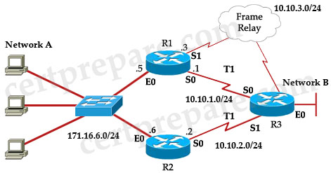
| R1# show running-config ! interface Ethernet0 ip address 171.16.6.5 255.255.255.0 standby 1 ip 171.16.6.100 standby 1 priority 105 standby 1 preempt standby 1 track Serial0 10 standby 1 track Serial1 10 ! interface Serial0 ip address 10.10.1.1 255.255.255.0 ! interface Serial1 ip address 10.10.3.3 255.255.255.0 ! |
R2# show running-config ! interface Ethernet0 ip address 171.16.6.6 255.255.255.0 standby 1 ip 171.16.5 100 standby 1 preempt standby 1 track Serial0 10 ! interface Serial0 ip address 10.10.2.2 255.255.255.0 ! |
A. R1 will change its priority but will remain active using the Frame Relay backup link to forward the traffic to Network B
B. R2 will assume the role of active router and will use its T1 link to forward the traffic to Network B
C. Both routers R1 and R2 will be active, and the traffic will be load balanced between the T1 links
D. Both routers R1 and R2 will be inactive, and the users on Network A will lose the connectivity to Network B
Answer: B
Explanation
On R1, interface E0 is configured with the priority of 105 (standby 1 priority 105) while interface E0 of R2 uses the default priority of 100 so R1 will become the active router. Both the routers are configured with “preempt” feature so if one of them has a higher priority than the active router, it assumes control as the active router.
Both the routers are configure to track interface S0 (connected R3 via T1 links) so if its T1 links fails, the hot standby priority on the device decreases by 10 (the default decrement value). In this case if T1 link connected to R1 fails its priority would be 105 – 10 = 95 and it is smaller than that of R2 (100, by default) so R2 will take the active role and send Network A traffic via its T1 link.
Question 7
Which high availability service is verified by the show standby command?
A. VRRP
B. GLBP
C. HSRP
D. MSTP
E. PVRST
Answer: C
Explanation
The syntax for VRRP and GLBP begins with “vrrp” and “glbp” respectively, for example: “vrrp 10 priority 110”; “glbp 10 priority 254” while the syntax for HSRP is “standby …”, for example “standby 1 ip 10.10.10.1”.
Question 8
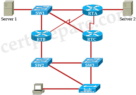
Observe the topology in the exhibit. HSRP is configured between RTB and RTC with RTC as the active router. SW2 is configured as the root bridge for the Spanning Tree Protocol. What will happen if the serial connection of RTC is down?
A. STP will not need to be recalculated because RTB will take over as active router
B. RTB and RTC will flap between active and standby because the timers for the STP are greater that the timers for HSRP
C. All traffic will automatically forward to RTB
D. SW3 will take over as the new root bridge
Answer: B
Explanation
To make the explanation easier we added port numbers to our routers and switches.
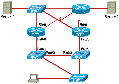
When S0/0 interface on RTC goes down, suppose RTC is tracking this interface and it is lost the active role. RTB will take the active role and turns on its Fa0/0 port. SW2 detects this link-state change and a spanning tree protocol transition takes place. The port Fa0/1 (on Sw2) takes approximately 30 seconds to go through the listening, learning, and forwarding stages. This time period exceeds the default timeouts of the HSRP hello processes so RTC, after reaching the Standby state, becomes Active because no hello packets were received from the RTB. Once again, the port Fa0/1 on Sw3 needs 30 seconds to reach final forwarding stage and that causes RTB tries to get the active role again -> Both RTB and RTC will flap between active and standby.
Note: HSRP changes its state when it fails to receive three consecutive HSRP hello packets from its peer. By default, hello timer is set to 3 seconds. That means a hello packet is sent between the HSRP standby group devices every 3 seconds, and the standby device becomes active when a hello packet has not been received for 10 seconds.(Reference: http://www.cisco.com/c/en/us/support/docs/ip/hot-standby-router-protocol-hsrp/13782-8.html)
Note: Physical link-state changes caused by HSRP state changes occur specifically on the network module-Fast Ethernet (NM-FE) interfaces on Cisco 2600, Cisco 3600 and Cisco 7200 series routers. This behavior no longer occurs in Cisco IOS® Software release 12.1(3) and higher.
Question 9
What is the maximum number of HSRP standby groups that can be configured on a Cisco router?
A. 16
B. 32
C. 64
D. 128
E. 256
Answer: E
Question 10
You have just purchased a new Cisco 3550 switch running the enhanced IOS and need to configure it to be installed in a high availability network. Which three types of interfaces can be used to configure HSRP on a 3550 EMI switch? (Choose three)
A – BVI interface
B – routed port
C – SVI interface
D – Access port
E – EtherChannel port channel
F – Loopback Interface
Answer: B C E
Explanation:
To configure HSRP, a Layer 3 interface is needed. They can be:
– Routed port: a physical port configured as a Layer 3 port by entering the no switchport interface configuration command.
– SVI: a VLAN interface created by using the interface vlan vlan_id global configuration command and by default a Layer 3 interface.
– Etherchannel port channel in Layer 3 mode: a port-channel logical interface created by using the interface port-channel port-channel-number global configuration command and binding the Ethernet interface into the channel group.
Reference: