InterVLAN Routing
Here you will find answers to InterVLAN Routing questions
Question 1
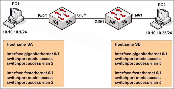
Study the exhibit carefully. Both host stations are part of the same subnet but are in different VLANs. On the basis of the information presented in the exhibit, which statement is true about an attempt to ping from host to host?
A – Layer 3 device is needed for the ping command to be successful.
B – A trunk port will need to be configured on the link between SA and SB for the ping command to be successful.
C – The two different hosts will need to be in the same VLAN in order for the ping command to be successful.
D – The ping command will be successful without any further configuration changes.
Answer: D
Explanation
When PC1 sends traffic to SA, SA realizes that PC1 belongs to VLAN 2 so it will forward out of its Gi0/1 port which also belongs to VLAN 2. On the other side, SB receives this frame coming from its Gi0/1 port so it believes this frame belongs to VLAN 5. SB will forward this frame out of its Fa0/1 which belongs to VLAN 5, too -> PC1 & PC2 can communicate without further configuration provided that they are in the same subnet (so they don’t need a Layer 3 device).
Question 2
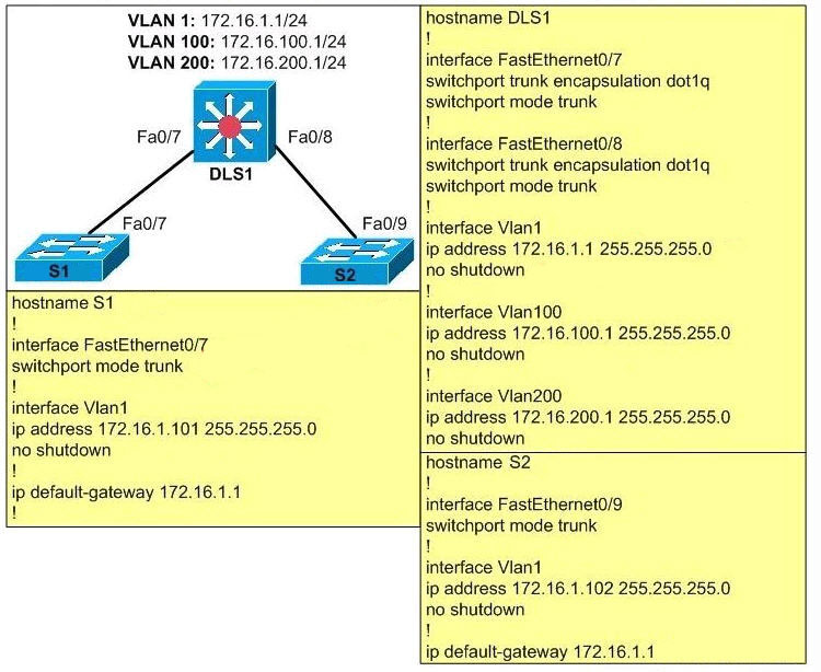
Based on the following exhibit, which problem is preventing users on VLAN 100 from pinging addresses on VLAN 200?
A – Native VLAN mismatch.
B – Subinterfaces should be created on Fa0/7 and Fa0/8 on DLS1.
C – Trunking needs to be enabled.
D – The ip routing command is missing on DLS1.
Answer: D
Explanation
To allow communication between two VLANs, we need to enables Layer 3 routing on the switch with the “ip routing” command. Some flatforms are enabled by default but some are not.
Question 3
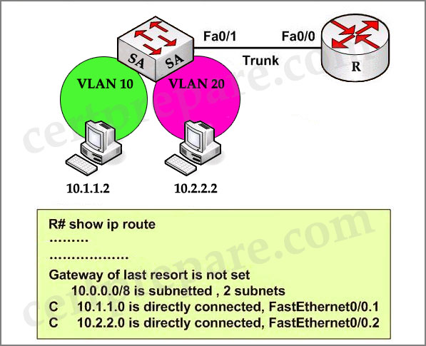
Based on the network diagram and routing table output in the exhibit, which one of these statements is true?
A – InterVLAN routing has been configured properly, and the workstations have connectivity to each other.
B – InterVLAN routing will not occur since no routing protocol has been configured.
C – Although interVLAN routing is not enabled, both workstations will have connectivity to each other.
D – Although interVLAN routing is enabled, the workstations will not have connectivity to each other.
E – None of the above.
Answer: A
Explanation
In the output we can see both VLAN10 and VLAN20 are shown up (as networks 10.1.1.0 and 10.2.2.0) so the routing has been configured properly. Notice that the “C” letter indicates that these networks are directly connected with the router.
Question 4
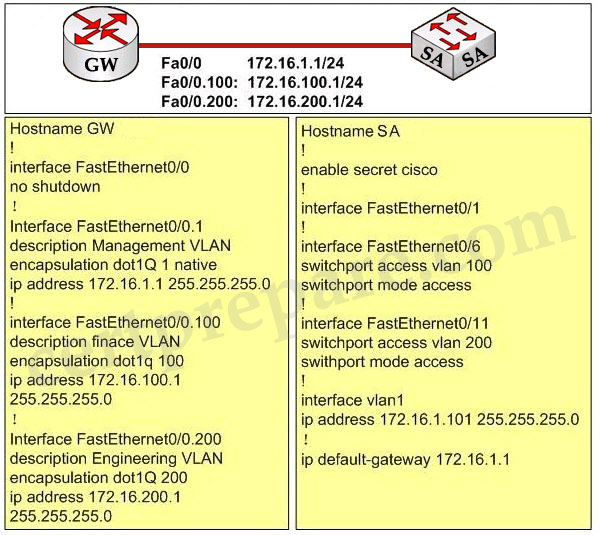
Study the following exhibit carefully, what is the reason that users from VLAN 100 can’t ping users on VLAN 200?
A – IP routing needs to be enabled on the switch
B – Trunking needs to be enabled on Fa0/1
C – VLAN 1 needs the no shutdown command
D – The native VLAN is wrong
Answer: B
Explanation
The Fa0/1 interface on the switch is not configured with trunking mode. It needs to be configured as shown below:
SA(config)#interface Fa0/1
SA(config-if)#switchport mode trunk
SA(config-if)#switchport trunk encapsulation dot1q
Question 5
Assume that a host sends a packet to a destination IP address and that the CEF-based switch does not yet have a valid MAC address for the destination. How is the ARP entry (MAC address) of the next-hop destination in the FIB get?
A – The sending host must send an ARP request for it
B – All packets to the destination are dropped
C – The Layer 3 forwarding engine (CEF hardware) must send an ARP request for it
D – CEF must wait until the Layer 3 engine sends an ARP request for it
Answer: D
Explanation
If a valid MAC address for the destination is not found, the Layer 3 forwarding engine can’t forward the packet in hardware due to the missing Layer 2 next-hop address. Therefore the packet is sent to the Layer 3 Engine so that it can generate an ARP request (this is called the “CEF glean” state).
Question 6
CEF is a complete new routing switch technology . Which two table types are CEF components? (Choose two)
A – adjacency tables
B – caching tables
C – neighbor tables
D – forwarding information base
Answer: A D
Explanation
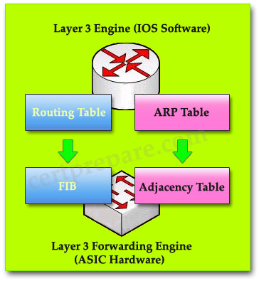
The two main components of CEF operation are:
+ Forwarding Information Base: is built from the Multilayer Switch’s routing table and is sorted to optimize searches.
+ Adjacency Tables: is built from Multilayer Switch’s ARP table. Nodes in the network are said to be adjacent if they can reach each other with a single hop across a link layer. In addition to the FIB, CEF uses adjacency tables to prepend Layer 2 addressing information. The adjacency table maintains Layer 2 next-hop addresses for all FIB entries.
Reference: http://www.cisco.com/c/en/us/support/docs/routers/12000-series-routers/47321-ciscoef.html.
Question 7
Refer to the exhibit.
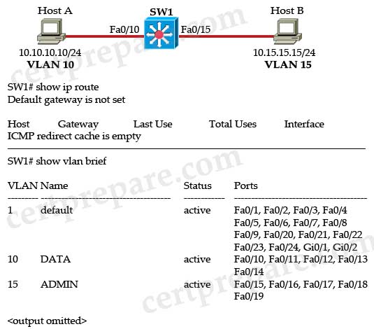
Host A and Host B are connected to the Cisco Catalyst 3550 switch and have been assigned to their respective VLANs. The rest of the 3550 configuration is the default configuration. Host A is able to ping its default gateway, 10.10.10.1, but is unable to ping Host B. Given the output in the exhibit, which statement is true?
A. HSRP must be configured on SW1.
B. A separate router is needed to support inter-VLAN routing.
C. Interface VLAN 10 must be configured on the SW1 switch.
D. The global configuration command “ip routing” must be configured on the SW1 switch.
E. VLANs 10 and 15 must be created in the VLAN database mode.
F. VTP must be configured to support inter-VLAN routing.
Answer: D
Explanation
To enable routing on a Layer 3 switch first we have to use the ip routing command. From the output of “show vlan brief” command above, we learn that ports connected to hosts have been configured as access ports and assigned to VLAN 10 & 15. The missing thing here is only the “ip routing” command. Below lists the full configuration so that these two hosts can communicate.
| ip routing ! interface FastEthernet0/10 switchport access vlan 10 switchport mode access ! interface FastEthernet0/15 switchport access vlan 15 switchport mode access ! interface Vlan10 ip address 10.10.10.1 255.255.255.0 ! interface Vlan15 ip address 10.15.15.1 255.255.255.0 |
Question 8
Which three statements about routed ports on a multilayer switch are true? (Choose three)
A. A routed port can support VLAN subinterfaces.
B. A routed port takes an IP address assignment.
C. A routed port can be configured with routing protocols.
D. A routed port is a virtual interface on the multilayer switch.
E. A routed port is associated only with one VLAN.
F. A routed port is a physical interface on the multilayer switch.
Answer: B C F
Explanation
A routed port is a physical port on a switch, that acts like a normal port on a router. It supports all routing protocols and can take an IP address assignment. It does not however support VLAN subinterfaces and it is also not associated with a single VLAN. It is configured on a port connected to a router. To configure a port on a switch Layer 3 a routed port, enter the “no switchport” command under interface mode.
A switch virtual interface (SVI) is not considered a routed port. SVIs support both routing and switching protocols, while routed ports do not support any layer 2 protocols (like STP).
Question 9
Which two statements describe a routed switch port on a multilayer switch? (Choose two)
A. Layer 2 switching and Layer 3 routing are mutually supported.
B. The port is not associated with any VLAN.
C. The routed switch port supports VLAN subinterfaces.
D. The routed switch port is used when a switch has only one port per VLAN or subnet.
E. The routed switch port ensures that STP remains in the forwarding state.
Answer: B D
Explanation
A routed switch port on a Layer 3 switch is same as a port on a router. By default, ports on a multilayer switch will all be running in Layer 2 mode. To configure a port as a routed port, use the “no switchport” command. From now, the port is not associated with any VLAN -> B is correct.
Also like ports in a router, each port can only belongs to one VLAN or subnet -> D is correct.
Question 10
Refer to the exhibit.
| Switch# show ip cef vlan 30 detail IP CEF with switching (Table Version 11), flags=0x0 10 routes, 0 reresolve, 0 unresolved (0 old, 0 new), peak 0 13 leaves, 12 nodes, 14248 bytes, 14 inserts, 1 invalidations 0 load sharing elements, 0 bytes, 0 references universal per-destination load sharing algorithm, id 4B936A24 2(0) CEF resets, 0 revisions of existing leaves Resolution Timer: Exponential (currently 1s, peak 1s) 0 in-place/0 aborted modifications refcounts: 1061 leaf, 1052 node Table epoch: 0 (13 entries at this epoch) 10.1.30.0/24, version 6, epoch 0, attached, connected 0 packets, 0 bytes via Vlan30,0 dependencies valid glean adjacency |
Which statement is true?
A. Cisco Express Forwarding load balancing has been disabled.
B. SVI VLAN 30 connects directly to the 10.1.30.0/24 network due to a valid glean adjacency.
C. VLAN 30 is not operational because no packet or byte counts are indicated.
D. The IP Cisco Express Forwarding configuration is capable of supporting IPv6.
Answer: B
Explanation
A glean adjacency entry indicates that a particular next hop should be directly connected, but there is no MAC header rewrite information available.
When a router is connected directly to several hosts, the FIB table on the router maintains a prefix for the subnet rather than for the individual host prefixes. The subnet prefix points to a glean adjacency. When packets need to be forwarded to a specific host, the adjacency database is gleaned for the specific prefix.
(A good resource: http://www.cisco.com/en/US/tech/tk827/tk831/technologies_white_paper09186a00800a62d9.shtml#express and http://www.cisco.com/c/en/us/support/docs/ip/express-forwarding-cef/13706-20.html)