In the SD-WAN overlay, virtual private networks (VPNs) provide segmentation. Each VPN is equivalent to a VRF, which is isolated from one another and have their own forwarding tables. An interface or subinterface is explicitly configured under a single VPN and cannot be part of more than one VPN. Devices attached to an interface in one VPN cannot communicate with devices in another VPN unless policy is put in place to allow it. The VPN ranges from 0 to 65535, but several VPNs are reserved for internal use.
The Transport & Management VPNs
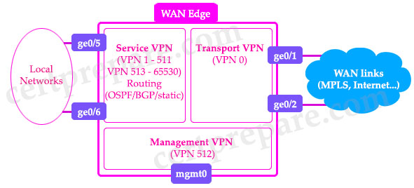
There are two implicitly configured VPNs in the WAN Edge devices and controllers: VPN 0 and VPN 512.
– VPN 0 is the transport VPN. It contains all the interfaces that connect to the (underlay) WAN links. Secure DTLS/TLS connections to the controllers are initiated from this VPN. Static or default routes or a dynamic routing protocol needs to be configured inside this VPN in order to get appropriate next-hop information so the control plane can be established and IPsec tunnel traffic can reach remote sites.
VPN 0 connects the WAN Edge to the WAN transport and creates control plane and data plane connections. The WAN Edge device can connect to multiple WAN transport(s) on different interfaces on the same VPN 0 transport segment. At least one interface needs to be configured to initially reach the SD-WAN controllers for onboarding.
– VPN 512 is the management VPN. It carries the out-of-band management traffic to and from the Cisco SD-WAN devices. This VPN is ignored by OMP and not carried across the overlay network.
READ MORE…
Bi-directional Forwarding Detection (BFD) is a extremely lightweight detection protocol that provides very fast forwarding-path failure detection for all media types, encapsulations, topologies, and the routing protocols (like BGP, EIGRP, IS-IS and OSPF). By using along with these routing protocols, BFD can greatly reduce network convergence time.
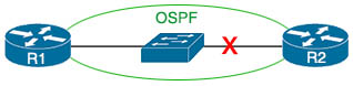
In the picture below, we see we have two routers R1 and R2 connected together through a layer 2 switch. These two routers are OSPF neighbors with each other. What if the physical interface between R2 and the layer 2 switch goes down?
READ MORE…
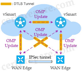
Cisco SD-WAN uses Overlay Management Protocol (OMP) which manages the overlay network. OMP runs between the vSmart controllers and WAN Edge routers (and among vSmarts themselves) where control plane information, such as the routing, policy, and management information, is exchanged over a secure connection. If no policy is defined, the default behavior of OMP is to allow a full mesh topology, where each WAN Edge router can connect directly to other WAN Edge routers.
Centralized policies are built using vManage, and then stored in its database. They are then sent via NETCONF to the vSmart controller to become a part of vSmart configurations. The vSmart controller then uses OMP to send the policy parameters as updates in the routing protocol to all of the WAN edge devices. WAN edge devices learn the policy and then execute them in memory. As a result, all configurations are backed up in vManage configuration database.
READ MORE…
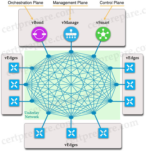
SD-WAN represents the shift from an older, hardware-based model of legacy WAN to a secure, software-based, virtual IP fabric overlay that runs over standard network transport services. The Cisco SD-WAN solution is comprised of separate orchestration, management, control, and data planes:
READ MORE…