Overlay Management Protocol OMP Tutorial
Cisco SD-WAN uses Overlay Management Protocol (OMP) which manages the overlay network. OMP runs between the vSmart controllers and WAN Edge routers (and among vSmarts themselves) where control plane information, such as the routing, policy, and management information, is exchanged over a secure connection. If no policy is defined, the default behavior of OMP is to allow a full mesh topology, where each WAN Edge router can connect directly to other WAN Edge routers.
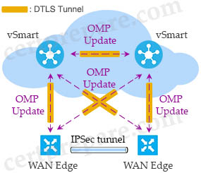
Centralized policies are built using vManage, and then stored in its database. They are then sent via NETCONF to the vSmart controller to become a part of vSmart configurations. The vSmart controller then uses OMP to send the policy parameters as updates in the routing protocol to all of the WAN edge devices. WAN edge devices learn the policy and then execute them in memory. As a result, all configurations are backed up in vManage configuration database.
OMP is a propriety protocol that is enabled by default in our Transport VPN (VPN0), so we do not need to configure anything to make it come up. As soon as our DTLS connections to our vSmart are established, our OMP peerings will automatically be formed and the exchange of routing information takes place.
OMP advertises three types of routes:
+ OMP routes are routes learned from the local site, or service side, of a vEdge router (via connected, static, OSPF or BGP…). The routes are redistributed into OMP so they can be carried across the overlay. OMP routes advertise attributes such as:
– Transport location (TLOC) information: which is similar to a BGP next-hop IP address for the route. TLOC is a 3 tuple value {System IP, Color, Encapsulation}:
— System IP is the address of the OMP speaker that originates the OMP route. It is a 32 bit number presented in the classic IPv4 dotted-decimal notation (which is equivalent to router-id in traditional routing protocols like OSPF)
— Color represents the type of WAN interfaces on vEdge router. The Cisco (Viptela) solution offers predefined colors, which are assigned in the configuration of the vEdge routers. The color can be one of default, 3g, biz-internet, blue, bronze, custom1, custom2, custom3, gold, green, lte, metro-ethernet, mpls, private1, private2, public-internet, red, and silver.
— Encapsulation type on the transport tunnel. It can be either IPsec or GRE.
– Origin: identifies the origin of the vRoute (whether route originated from BGP, OSPF, Connected or Static…) along with the metric of the original route.
– Originator: IP address from which the route has propagated.
– Preference: If two similar OMP protocol routes exist, the one with higher preference is preferred. Default is 0.
– Service: Network service associated with the OMP protocol route.
– Site-ID: Identifier of the site from which the OMP route is propagated.
– Tag: Optional which can be used to match a specific route and then take necessary action on that.
– VPN: VPN-ID in which the route has been propagated.
An OMP route is only installed in the forwarding table if the TLOC to which it points is active.
+ TLOC routes are the logical tunnel termination points on the vEdge routers that connect into a transport network. A TLOC route is uniquely identified and represented by a three-tuple, consisting of system IP address, link color, and encapsulation (Generic Routing Encapsulation [GRE] or IPSec). In addition to system IP address, color, and encapsulation, TLOC routes also carry attributes such as TLOC private and public IP addresses, carrier, preference, site ID, tag, and weight. For a TLOC to be considered in an active state on a particular vEdge, an active BFD session must be associated with that vEdge TLOC.
+ Service routes represent services (firewall, IPS, application optimization…) that are connected to the vEdge local-site network and are available for other sites for use with service insertion. In addition, these routes also include VPNs; the VPN labels are sent in this update type to tell the vSmart controllers what VPNs are serviced at a remote site.
Let’s take an example:
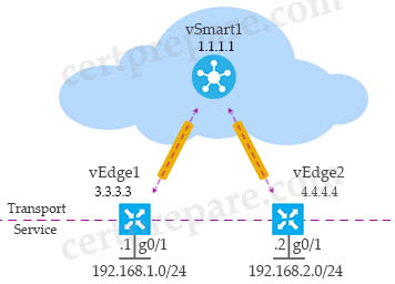
In the above topology, notice that the system IP of vSmart1 is 1.1.1.1. We can check all the OMP peers of vEdge1 router with the “show omp peers” command:
vEdge1#show omp peers
R -> routes received
I -> routes installed
S -> routes sent
                        DOMAIN      OVERLAY   SITE
PEER        TYPE        ID          ID        ID      STATE     UPTIME       R/I/S
-------------------------------------------------------------------------------------
1.1.1.1     vsmart      1           1         100     up        0:02:11:22   1/1/1
As we can see, only vSmart1 is the OMP peer of vEdge1 with the System IP of 1.1.1.1. It is in “up” state. Notice that vEdge1 does not establish OMP peer with vEdge2.
In the last column (R/I/S) we see vEdge1 received (“R” letter in the last column) one route and installed it (“I”) into OMP routing table. It also sent one route (“S”) to vSmart1.
To check the detail of which route was installed into OMP routing table of vEdge1, we can use the command “show omp routes”:
vedge1#show omp routes
Code:
C   -> chosen
I   -> installed
Red -> redistributed
Rej -> rejected
L   -> looped
R   -> resolved
S   -> stale
Ext -> extranet
Inv -> invalid
Stg -> staged
U   -> TLOC unresolved

                                            PATH                      ATTRIBUTE
VPN    PREFIX              FROM PEER        ID     LABEL    STATUS    TYPE       TLOC IP          COLOR            ENCAP  PREFERENCE
--------------------------------------------------------------------------------------------------------------------------------------
1      192.168.1.0/24      0.0.0.0          65     1003     C,Red,R   installed  3.3.3.3          default          ipsec  -
1      192.168.2.0/24      1.1.1.1          1      1003     C,I,R     installed  4.4.4.4          default          ipsec  -
From the last line of the output above, we can see the prefix 192.168.2.0/24 was learned from TLOC {4.4.4.4, default, ipsec}. Remember that TLOCs are defined by three tuple value {System IP, Color, Encapsulation}.
We also see our local prefix 192.168.1.0/24 was redistributed (“Red” in the “Status” column) automatically into OMP and it is the route that vEdge1 advertised to vSmart1 because it is a (directly) connected route.
| Note: OMP automatically redistributes the following types of routes that it learns either locally or from its routing peers: Connected, Static, OSPF intra-area routes, OSPF inter-area routes. |
The prefix 192.168.2.0/24 was learned from TLOC {4.4.4.4, default, ipsec} so in order to reach 192.168.2.0/24 network, vEdge1 must find information from TLOC {4.4.4.4, default, ipsec}. We can check the detail of this TLOC with the “show omp tlocs” command:
vedge1# show omp tlocs
Code:
C   -> chosen
I   -> installed
Red -> redistributed
Rej -> rejected
L   -> looped
R   -> resolved
S   -> stale
Ext -> extranet
Stg -> staged
Inv -> invalid

                                                                                                                                       PUBLIC           PRIVATE
                                                                    PSEUDO                   PUBLIC                   PRIVATE  PUBLIC  IPV6    PRIVATE  IPV6     BFD
TLOC IP          COLOR            ENCAP  FROM PEER        STATUS    KEY     PUBLIC IP        PORT    PRIVATE IP       PORT     IPV6    PORT    IPV6     PORT     STATUS
-------------------------------------------------------------------------------------------------------------------------------------------------------------------------
3.3.3.3          default          ipsec  0.0.0.0          C,Red,R   1       10.10.20.60      12366   10.10.20.60      12366    ::      0       ::       0        up
4.4.4.4          default          ipsec  1.1.1.1          C,I,R     1       10.10.20.61      12366   10.10.20.61      12366    ::      0       ::       0        up
All the information to reach this TLOC{4.4.4.4, default, ipsec} is listed in the last line with Public IP of 10.10.20.61, public port of 12366.
Finally let’s check the routing table of vEdge1 to see all the routes learned by vEdge1 with the “show ip route” command:
vedge1# show ip route
Codes Proto-sub-type:
  IA -> ospf-intra-area, IE -> ospf-inter-area,
  E1 -> ospf-external1, E2 -> ospf-external2,
  N1 -> ospf-nssa-external1, N2 -> ospf-nssa-external2,
  e -> bgp-external, i -> bgp-internal
Codes Status flags:
  F -> fib, S -> selected, I -> inactive,
  B -> blackhole, R -> recursive

                                            PROTOCOL  NEXTHOP     NEXTHOP          NEXTHOP
VPN    PREFIX              PROTOCOL         SUB TYPE  IF NAME     ADDR             VPN      TLOC IP          COLOR            ENCAP  STATUS
---------------------------------------------------------------------------------------------------------------------------------------------
0      0.0.0.0/0           static           -         ge0/0       10.10.20.254     -        -                -                -      F,S
0      3.3.3.3/32          connected        -         system      -                -        -                -                -      F,S
0      10.10.20.0/24       connected        -         ge0/0       -                -        -                -                -      F,S
1      192.168.1.0/24      connected        -         ge0/1       -                -        -                -                -      F,S
1      192.168.2.0/24      omp              -         -           -                -        4.4.4.4          default          ipsec  F,S
There is only one prefix 192.168.2.0/24 was learned via OMP.
Note: The prefix 10.10.20.0/24 on interface G0/0 is only used to SSH to this device for configuration.
We can ping from vEdge1 to 192.168.2.0/24 network on vEdge2:
vedge1# ping vpn 1 192.168.2.2 count 4
Ping in VPN 1
PING 192.168.2.2 (192.168.2.2) 100(128) bytes of data.
108 bytes from 192.168.2.2: icmp_seq=1 ttl=64 time=0.449 ms
108 bytes from 192.168.2.2: icmp_seq=2 ttl=64 time=0.214 ms
108 bytes from 192.168.2.2: icmp_seq=3 ttl=64 time=0.218 ms
108 bytes from 192.168.2.2: icmp_seq=4 ttl=64 time=0.241 ms

--- 192.168.2.2 ping statistics ---
5 packets transmitted, 5 received, 0% packet loss, time 4000ms
rtt min/avg/max/mdev = 0.214/0.267/0.449/0.093 ms
Reference: https://explore.cisco.com/sd-wan-adopt/cvd-sd-wan-design-colors#page=7
Reference: https://www.cisco.com/c/dam/en/us/td/docs/solutions/CVD/SDWAN/sdwan-dia-deploy-2019nov.pdf